
Twin-Connection Flanged-Base Fire Department Connection — UF-020 / UF-022
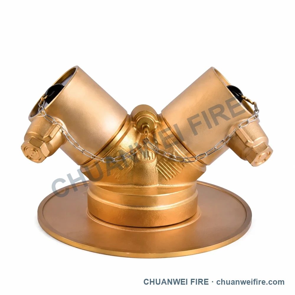
Connection or dimension references: inlet 4 in NPT; outlet 2.5 in BS336 · inlet 4 in BSP; outlet 2.5 in BS336
4 configurations to compare
Use the configuration images to identify the required product, then confirm connection, material and performance data with the quotation.
Configuration images are illustrations. Request the product photo, connection and performance details for your selected configuration before ordering.
Connection or dimension references: inlet 4 in NPT; outlet 2.5 in BS336 · inlet 4 in BSP; outlet 2.5 in BS336
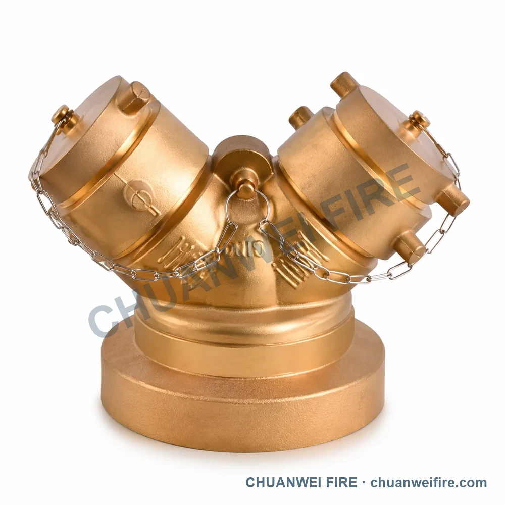
Connection or dimension references: inlet 6 in NPT; outlet 2.5 in NH · inlet 6 in BSP; outlet 2.5 in NH
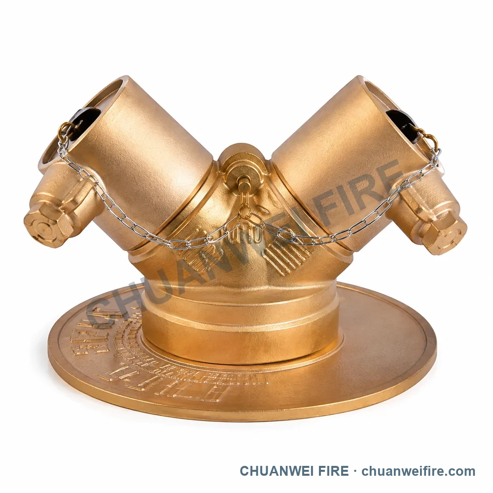
Connection or dimension references: inlet 4 in NPT; outlet 2.5 in NH · inlet 4 in BSP; outlet 4 in BSP
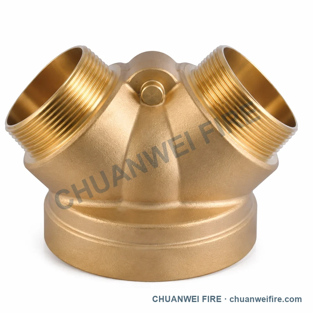
Connection or dimension references: inlet 4 in BSP; outlet 2.5 in BSP · inlet 4 in NPT; outlet 2.5 in NH
Configuration images
Illustrations for comparing available configurations. Request the product photo and drawing for your selected configuration to confirm connections and dimensions.
Specifications
Compare connection and dimension references to choose your configuration. Final order specifications are confirmed with the quotation.
Available configurations
Compare the configuration and connection or dimension references in each row.
| Configuration | Connection or dimension references |
|---|---|
| Twin-Connection Flanged-Base Fire Department Connection — UF-020 / UF-022 | inlet 4 in NPT; outlet 2.5 in BS336 · inlet 4 in BSP; outlet 2.5 in BS336 |
| Twin-Cap Heavy-Base Fire Department Connection — UF-023 / UF-024 | inlet 6 in NPT; outlet 2.5 in NH · inlet 6 in BSP; outlet 2.5 in NH |
| Twin-Cap Flanged-Base Fire Department Connection — UF-025 / UF-026 | inlet 4 in NPT; outlet 2.5 in NH · inlet 4 in BSP; outlet 4 in BSP |
| Twin Male-Threaded Fire Department Connection — UF-030 / UF-031 | inlet 4 in BSP; outlet 2.5 in BSP · inlet 4 in NPT; outlet 2.5 in NH |
Compare the specifications for each named configuration below. Values apply only to the configuration shown.
Dual-clapper configuration with female swivel inlets. Select the exact thread and system connection before ordering.
Confirm the mating connection from the required drawing or sample before ordering.
Inlet designation and nominal flange size for this configuration only. Flange drilling is selected separately.
Confirm the mating connection from the required drawing or sample before ordering.
Quotation confirmation
Start with the configuration and quantity. Add size, connection, working pressure and destination when available; we will review the supply details with you.
Start with the configuration and quantity. Size, connection and project requirements can follow.