
Horizontal-Handwheel Fire Hose Valve — GV-011 / GV-012
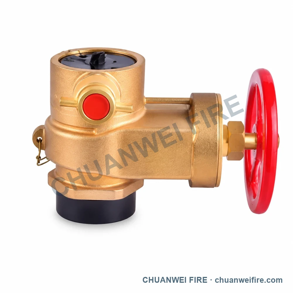
Connection or dimension references: inlet 2.5 in BSP; outlet 2.5 in BS336 · inlet 2.5 in BS4504; outlet 2.5 in BS336
5 configurations to compare
Use the configuration images to identify the required product, then confirm connection, material and performance data with the quotation.
Configuration images are illustrations. Request the product photo, connection and performance details for your selected configuration before ordering.
Connection or dimension references: inlet 2.5 in BSP; outlet 2.5 in BS336 · inlet 2.5 in BS4504; outlet 2.5 in BS336
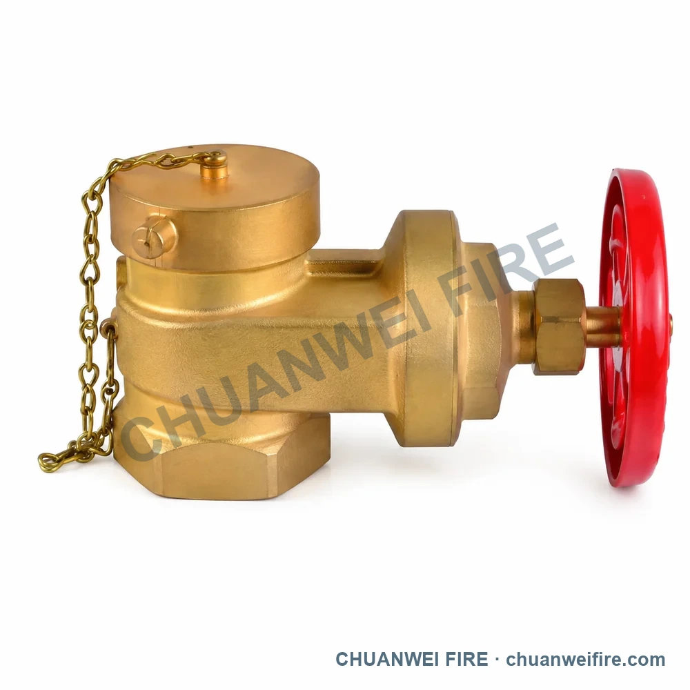
Connection or dimension references: inlet 2.5 in NPT; outlet 2.5 in NH
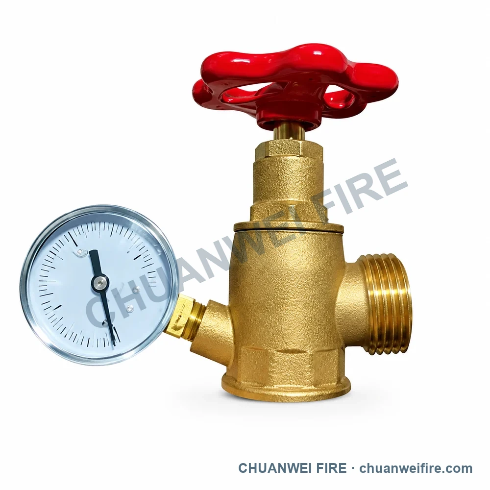
Connection or dimension references: inlet 1 in BSP; outlet 1 in BSP · inlet 1.5 in BSP; outlet 1.5 in BSP
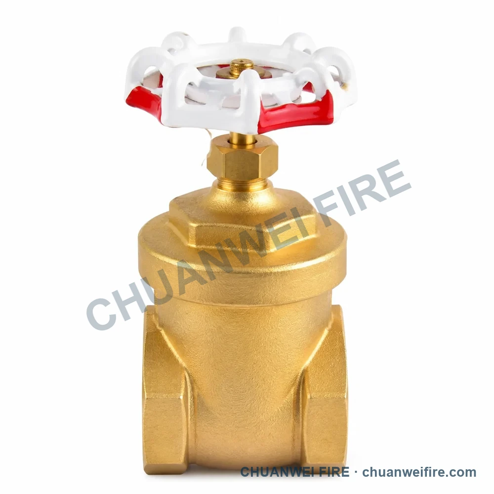
Connection or dimension references: inlet 1 in -4 in BSP; outlet 1 in -4 in BSP; alternate 1 in -4 in NPT / 1 in -4 in NPT
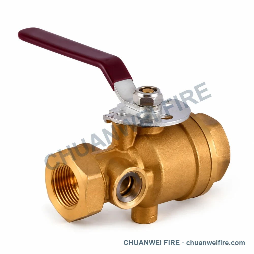
Connection or dimension references: inlet 1 in BSP; outlet 1 in BSP · inlet 1.2 in BSP; outlet 1.2 in BSP · inlet 1.5 in BSP; outlet 1.5 in BSP · inlet 2 in BSP; outlet 2 in BSP
Configuration images
Illustrations for comparing available configurations. Request the product photo and drawing for your selected configuration to confirm connections and dimensions.
Specifications
Compare connection and dimension references to choose your configuration. Final order specifications are confirmed with the quotation.
Available configurations
Compare the configuration and connection or dimension references in each row.
| Configuration | Connection or dimension references |
|---|---|
| Horizontal-Handwheel Fire Hose Valve — GV-011 / GV-012 | inlet 2.5 in BSP; outlet 2.5 in BS336 · inlet 2.5 in BS4504; outlet 2.5 in BS336 |
| Horizontal-Handwheel Fire Hose Valve — GV-013 | inlet 2.5 in NPT; outlet 2.5 in NH |
| Valve with Pressure Gauge — S-131 | inlet 1 in BSP; outlet 1 in BSP · inlet 1.5 in BSP; outlet 1.5 in BSP |
| Straight-Through Handwheel Valve — BV-014 | inlet 1 in -4 in BSP; outlet 1 in -4 in BSP; alternate 1 in -4 in NPT / 1 in -4 in NPT |
| Long-Lever Ball Valve — BV-010 / BV-011 / BV-012 / BV-013 | inlet 1 in BSP; outlet 1 in BSP · inlet 1.2 in BSP; outlet 1.2 in BSP · inlet 1.5 in BSP; outlet 1.5 in BSP · inlet 2 in BSP; outlet 2 in BSP |
Compare the specifications for each named configuration below. Values apply only to the configuration shown.
Single-valve configuration with Russian-pattern quick coupling. These values do not apply to the twin-valve 65-16K-65 product.
Confirm the mating connection from the required drawing or sample before ordering.
Single-valve configuration with Russian-pattern quick coupling. These values do not apply to the twin-valve 65-16K-65 product.
Confirm the mating connection from the required drawing or sample before ordering.
Pressure and thread family for the sight-glass configuration. The final size and test orifice are selected for the order.
Select one factory reference below. Connection size and thread are confirmed for the exact supplied assembly.
Quotation confirmation
Start with the configuration and quantity. Add size, connection, working pressure and destination when available; we will review the supply details with you.
Start with the configuration and quantity. Size, connection and project requirements can follow.